So found out the reason why it was blowing all that smoke. I managed to install ALL of the middle piston rings upside-down, and some of the compression rings upside down too!
So I took the engine apart, all the way down to the piston and rings, then reassembled the rings on the pistons, reassembled the engine, and started it up! TaDA!! It runs and no smoke!!
Have been busy doing some tuning. So far, I am upto about 8.5psi... and that will be my base boost level. It is already SOOOO powerful! I cant wait to goto 18! Its going to be just insane!!
Will take some pictures and also a video soon.. I wonder if I can post videos on these blogs??
Stay tuned, hopefuly with a dynosheet that reads 300whp+!
Thursday, June 28, 2007
Sunday, June 3, 2007
Dont know what this is??
Well, I finally got the engine to idle... YAY! For about 15 minutes, then the garage was filled with white smoke... Boo! I also noticed black soot was dripping from my engine. It was suggested (by the friendly people on SpyderChat), that I may have cracked my head, the short block, or the head gasket... Well... so I started pulling the car apart again.
 Sooo much sooot!! Black stuff was being spat out everywhere...
 Having a look carefully at the valves, cylinder 1 exhaust valves appears brand new!! They looked like they have just been installed!
 Versus, cylinder 4 exhaust valve, which is white, which is the normal colour a properly operating combustion camber exhaust valve should look.
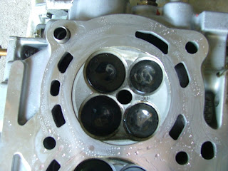 Cylinder 1 valves after I took the head off... Its even still got the installer's pen markings on it, in white! Obviously this cylinder has not been firing AT ALL.
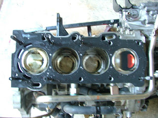 Look at the nice mix of oil and coolant in cyliner 1... Black and red... surprised I didnt have milk shake in my oil or coolant system.
Tuesday, May 15, 2007
Good News!
Well, this has been a good few days and a really bad one too today! I made lots of progress in the past week. Going from assembling the head to putting the engine back together, putting the transmission on, and getting it all back on the car!
The good news is that the manual conversion worked!! No manual harness needed, just a few wiring modifications to the starting circuit. Also, the shifter fork needs to be slightly modified somewhat so that the slave cylinder has got something on the end of the fork to push against (I welded a nut onto the end of the fork, cut the end bit of a stud off, and screwed the stud into the nut. The rod of the slave cylinder then pushes against the small bit of stud inside the nut. Works like a charm!
Anyway, on with the show!
 These things are called shims. They are like upside down cups that fit over the valve / spring / retainer assembley. The cam lobes then push on the shims to open the valves. The problem is, all the shims are different thicknesses!!!!!! Absolute pain in the arse to get the clearance right. All exhaust side clearances need to be 0.25-0.35mm, and all intake side need to be 0.15-0.25mm.
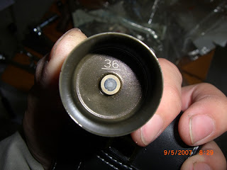 So here is one of the shims. The are all 5.XXmm, so this particular one is 5.36mm thick.
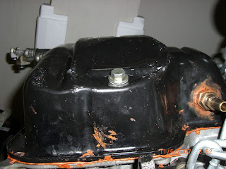 Superfically, it looked like only the oil pan was damaged. So I went to Mr T, and got another one, and made the same oil return fitting for the turbo. No dramas! Well! Read on...
 So I happily went about putting the transmission back on... fine... looked okay.
 Got the engine back in the car... lining up the engine mounts was a ABSOLUTE bitch! Took almost 5 hours to get the first bolt in. Once it was in, I hooked up the accelerator cable... needed to adjust the length of it as can be seen here. Otherwise, the throttle will only open 40% when the accelerator is fully depressed.
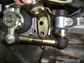
 Hooked up the shifter control cables... one of the cables proved to be TOO long... and as a result, the shifter ran out of room on the left to be able to shift into reverse... after fiddling around with the control cables for a long time, I realised that you just cant adjust the length of these things... so, I "shortened" it like so!
 This is just a picture from underneath the car, showing the slave cylinder and the shifter fork.
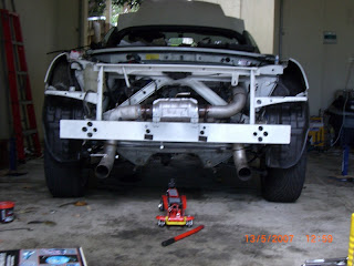 Well, an EXCITING moment for me! The car stands on its own four wheels again!! Alas, when I tried to crank the engine up, it didnt want to! After much research, I found the wiring diagram for the starter circuit.
 This is the starter circuit diagram. Because I am still using the SMT wiring loom, the ST relay was not getting any power when I turned the key. So what I did was I added two additional electrical connections. These are shown in red on the diagram.
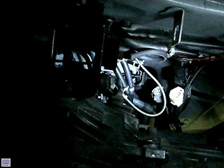
 This picture shows where the harness "IC1" is located. Connect the 7th pin with terminal 1 of the ST relay in the engine compartment fuse box.
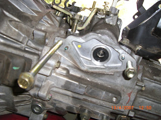
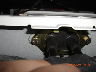
 The connect terminal 2 of the ST relay to the grounding spot shown here (near the ECUs).
The good news is that the manual conversion worked!! No manual harness needed, just a few wiring modifications to the starting circuit. Also, the shifter fork needs to be slightly modified somewhat so that the slave cylinder has got something on the end of the fork to push against (I welded a nut onto the end of the fork, cut the end bit of a stud off, and screwed the stud into the nut. The rod of the slave cylinder then pushes against the small bit of stud inside the nut. Works like a charm!
Anyway, on with the show!
 These things are called shims. They are like upside down cups that fit over the valve / spring / retainer assembley. The cam lobes then push on the shims to open the valves. The problem is, all the shims are different thicknesses!!!!!! Absolute pain in the arse to get the clearance right. All exhaust side clearances need to be 0.25-0.35mm, and all intake side need to be 0.15-0.25mm.
 So here is one of the shims. The are all 5.XXmm, so this particular one is 5.36mm thick.
 Superfically, it looked like only the oil pan was damaged. So I went to Mr T, and got another one, and made the same oil return fitting for the turbo. No dramas! Well! Read on...
 So I happily went about putting the transmission back on... fine... looked okay.
 Got the engine back in the car... lining up the engine mounts was a ABSOLUTE bitch! Took almost 5 hours to get the first bolt in. Once it was in, I hooked up the accelerator cable... needed to adjust the length of it as can be seen here. Otherwise, the throttle will only open 40% when the accelerator is fully depressed.
 Hooked up the shifter control cables... one of the cables proved to be TOO long... and as a result, the shifter ran out of room on the left to be able to shift into reverse... after fiddling around with the control cables for a long time, I realised that you just cant adjust the length of these things... so, I "shortened" it like so!
 This is just a picture from underneath the car, showing the slave cylinder and the shifter fork.
 Well, an EXCITING moment for me! The car stands on its own four wheels again!! Alas, when I tried to crank the engine up, it didnt want to! After much research, I found the wiring diagram for the starter circuit.
 This is the starter circuit diagram. Because I am still using the SMT wiring loom, the ST relay was not getting any power when I turned the key. So what I did was I added two additional electrical connections. These are shown in red on the diagram.
 This picture shows where the harness "IC1" is located. Connect the 7th pin with terminal 1 of the ST relay in the engine compartment fuse box.
 The connect terminal 2 of the ST relay to the grounding spot shown here (near the ECUs).
 Once these connections are made, the starter motor should start without any problems! Just remember to be on neutral when you start, as there are no fail safes here!
Well, I managed to get the car started and idling... but I noticed a rather rapid coolant leak, and it looked like it was dripping out of the oil pan... so I crawled underneath the car, but failed to see where the coolant was coming from.
What I did notice was consistent white smoke coming out of the exhuast, and also the coolant that had leaked to the ground appears to be somewhat oily!! Also, there were coolant dripping out of the exhuast pipe! All signs of a very unhealthy engine... looks like the engine "drop" will cost me more time and money after all!
However, lets look on the bright side, the SMT --> manual conversion worked!! I managed to roll the car fowards and backwards when the engine was running. It proved that the conversion did its job!
Saturday, May 5, 2007
Update!
Well, have been on holidays, and since I got back, I havent gotten around to posting my progress. In short, the car is in the reassembly process. The engine block is done, only waiting for one of the valve shims (the clearance between one of the intake valve shims and the intake cam lobe is out of spec).. the factory specification requires 0.15-0.25mm of clearance... this one is 0.05mm... getting the clearance of the shims right is a bit of a pain in the arse... but if you are planning on changing your valves and springs, expect that you will need to buy new shims. Unfortunately, there is no better way of finding out what depth shims you'll need until you start the reassembly process.
Ok, so on with the picture show! :-)
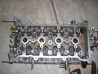 First, the head was disassembled... See the springs and retainers in the head? Well, over that assembley sits a shiney upside down metallic cup, called a shim. Note that the shims are ALL different thicknesses, so if you are planning on using the same springs and valves, then remember where each shim go!!
 Picture of the springs and retainers.... MWR sent me the wrong ones! However, the mistake was quickly rectified.. a happy customer once again. This delayed the process by around a week.
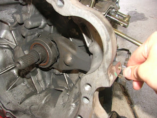
 So in the mean time, I started working on the manual conversion. I had gotten all my manual bits and bobs (except the big long clutch flexible hose.. long long long story! I eventually got one custom made and it costed me $57 dollars! Should have done that in the first place, instead of waiting almost 3 months to get one.) Anyway, the shifter cable brackets fit perfectly, except my SMT tranny is missing two holes for bolts.
 Also, I had to block up the hole at the back where the SMT assembley used to screw onto.
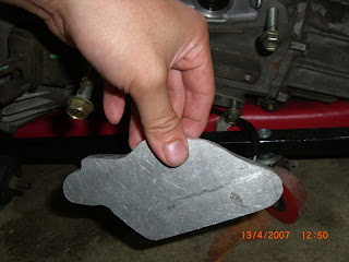 So a plate (made of aluminium) was made, and I drilled some holes my self and grinded away for a while on it...
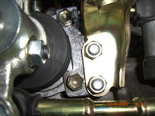 I got a plate made up which bolts onto to existing holes on the transmission, then drilled two additional holes to that the bracket has somewhere to secure onto.
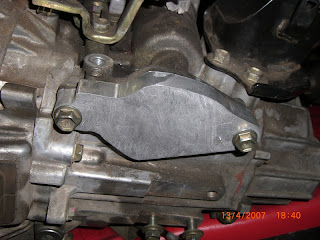 End result of the custom fabricated aluminium plate to block out the hole at the front of the transmission. Used some sealant to ensure that it is completely sealed and I wont get transmission fluids leaking!
 The next job was to drill an oval hole in the firewall... man, was this a b!tch of a job! Took me a whole day to get the holes there. I ended up using the side of a large drill bit to 'chip' away at the firewall, after I made the initial pilot holes. Those drill bits which are hollow on the inside, but has teeth on the outside just dont work! The teeths just keep getting rounded off!
 Ahh... a preview of whats to come! My manual shifter! The electrical plugs are for the SMT shifter, but obviously I dont have one now, so will just leave those hanging there!
 The block bored by 0.5mm, rehoned, and new pistons are in place! Looks great! Nice and shiney. :-)
 Side view of the short block and the bottom end assembled.
 Dont so what I did and overtorque the stud that holds the oil pickup in place. Its only 9lbs! I ended up snapping one, and having to get a new one.
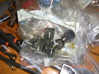
 Now, onto upgrading the fuel pump to a higher rated one. Wasnt too bad a task... just need to be careful as it is a bit fiddley.
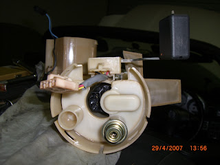
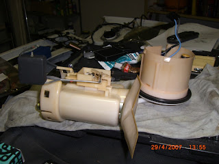 Separate the top and bottom end of the fuel pump assembley. The fuel pump sits in the bottom half of the assembley and connected directly to that L shaped 'pouch'.. thats a filter to keep all the crap out of your injectors.
 The fuel pump assembley can be found directly behind the driver (left hand drive!) seat.
 Side view of the block with the top end assembled as well. I will need to disassemble the camshaft again early next week when my new shim comes in. Oh, and the oil pump (the thing that the crank shaft goes through, is also a higher flow TOGA one.
Ok, so on with the picture show! :-)
 First, the head was disassembled... See the springs and retainers in the head? Well, over that assembley sits a shiney upside down metallic cup, called a shim. Note that the shims are ALL different thicknesses, so if you are planning on using the same springs and valves, then remember where each shim go!!
 Picture of the springs and retainers.... MWR sent me the wrong ones! However, the mistake was quickly rectified.. a happy customer once again. This delayed the process by around a week.
 So in the mean time, I started working on the manual conversion. I had gotten all my manual bits and bobs (except the big long clutch flexible hose.. long long long story! I eventually got one custom made and it costed me $57 dollars! Should have done that in the first place, instead of waiting almost 3 months to get one.) Anyway, the shifter cable brackets fit perfectly, except my SMT tranny is missing two holes for bolts.
 Also, I had to block up the hole at the back where the SMT assembley used to screw onto.
 So a plate (made of aluminium) was made, and I drilled some holes my self and grinded away for a while on it...
 I got a plate made up which bolts onto to existing holes on the transmission, then drilled two additional holes to that the bracket has somewhere to secure onto.
 End result of the custom fabricated aluminium plate to block out the hole at the front of the transmission. Used some sealant to ensure that it is completely sealed and I wont get transmission fluids leaking!
 The next job was to drill an oval hole in the firewall... man, was this a b!tch of a job! Took me a whole day to get the holes there. I ended up using the side of a large drill bit to 'chip' away at the firewall, after I made the initial pilot holes. Those drill bits which are hollow on the inside, but has teeth on the outside just dont work! The teeths just keep getting rounded off!
 Ahh... a preview of whats to come! My manual shifter! The electrical plugs are for the SMT shifter, but obviously I dont have one now, so will just leave those hanging there!
 The block bored by 0.5mm, rehoned, and new pistons are in place! Looks great! Nice and shiney. :-)
 Side view of the short block and the bottom end assembled.
 Dont so what I did and overtorque the stud that holds the oil pickup in place. Its only 9lbs! I ended up snapping one, and having to get a new one.
 Now, onto upgrading the fuel pump to a higher rated one. Wasnt too bad a task... just need to be careful as it is a bit fiddley.
 Separate the top and bottom end of the fuel pump assembley. The fuel pump sits in the bottom half of the assembley and connected directly to that L shaped 'pouch'.. thats a filter to keep all the crap out of your injectors.
 The fuel pump assembley can be found directly behind the driver (left hand drive!) seat.
  Side view of the block with the top end assembled as well. I will need to disassemble the camshaft again early next week when my new shim comes in. Oh, and the oil pump (the thing that the crank shaft goes through, is also a higher flow TOGA one.
 So, the project has stalled a little in the last month due to me waiting for the clutch line to come from Japan. Just a hint for anybody else doing this... dont bother ordering the clutch line from Toyota! I initially ordered it from the US (this was back in December last year, just before xmas!)... Toyota parts in the US finally contacted me in Feb saying that they were shipping all my parts out, but because the clutch line was so long, it would have changed the shipping cost significantly. So, I told them not to worry about sending the clutch line through, instead, I ordered the clutch line locally from our local Toyota dealership. The clutch line was ordered around the 14th March. They said it was going to be 4 weeks before it arrived here. Well, 8 weeks later, I got a call from Toyota, telling me that it was going to be another 4 more weeks because something went wrong at their warehouse and they stuffed up the order... So, I gave up at that point, told them to refund my deposit, and went to ABS breaks and clutch (in Osborne Park), who made up the line I needed in... oh.. 2 hours, and $57 AUD!
As a dear friend of mine told me, the solution is sometimes a lot closer to you than you think! Live and learn! :-)
Ok, will get back to my more regular updates. Keep your eye out for a video of the engine running! :-)
Signing out!
Friday, March 9, 2007
Its a BENT ROD too!
So I went out to get myself a putty knife and started cutting away at the oil pan / block seal. Got that off fairly quickly.
 Took the oil pickup off to so I could get at the rods.
Took the oil pickup off to so I could get at the rods. Rods were easy enough to get out... Much easier than I thought... Remember from my previous post, the piston in cylinder number 1 never quite made it all the way to the top, and I couldnt understand why??
 Well, this is why!! BENT Rod!! I couldnt believe that my engine was still running though! It turned over easily enough, and there were no combustion chamber leaks anywhere... This is very odd, considering that most bent rods would have caused major scoring of the cylinder walls and it would have been blow-by heaven! (blow-by is where the oil from the crank case gets into the combustion chamber because of either faulty rings, or too much clearance between the ring and the cylinder walls.
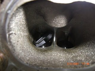
 Upon closer inspection of the cyliner walls, I found a little notch at the base of cylinder number 1. This notch must have been made by the force of the bent rod stiking into the cylinder walls... This would have also caused some rather unsettling engine noise!
 A closer look! I think I may be REALLY lucky here. Dont think I will need to sleeve this cylinder because the top two rings on the new WISECO pistons will never get as low as where the notch is, so I shouldnt have any sealing issues.... I think!
Saturday, March 3, 2007
The Engine Tick - I Found It!
So, finally got that triple-square (double-hex) tool that I've ordered... It works like magic! Well, I suppose it was designed to be used on those head studs... So lesson learnt, dont try to use an allen key, it wont work! Anyway, the triple square even got the rounded off head stud off! It took a little bit of light hammering, but once the triple square bit was in there, it turned the rounded off stud with little effort. So I separated the head from the rest of the block... finally!
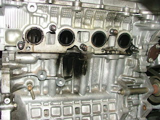
A few discoveries...
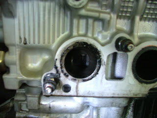
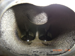
 Cylinder 1 - WTF! Little plastic bit jammed in the intake tract.
 Cylinder 2 - Normal
 Cylinder 3 - Normal
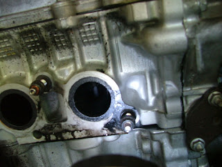
 Cylinder 4 - Another little plastic bit jammed in the intake tract.
So, this was what was causing the ticking noises from the head! It must have been the valves hitting the plastic on the way up... Also, did a careful examination of the cylinder bores and pistons... Everytime I did a compression test, one of the cylinders always came up a little lower then the others...
 Heres the visual proof of this! Compare the positions of the two outer pistons. Note how the left piston is not REALLY at TDC, while the right most piston is... Probably explains why I never managed to get over 200whp, even when running 10.5 psi!
Now, have gotten to the stage where I can really do no more on the engine without the right tools. Will be calling a friend for access to his facilities! :-)
Also, still waiting for the last of the manual conversion parts to come in... the shifter shaft is still not here, nor are the clutch lines... *sigh*
A few discoveries...
 Cylinder 1 - WTF! Little plastic bit jammed in the intake tract.
 Cylinder 2 - Normal
 Cylinder 3 - Normal
 Cylinder 4 - Another little plastic bit jammed in the intake tract.
So, this was what was causing the ticking noises from the head! It must have been the valves hitting the plastic on the way up... Also, did a careful examination of the cylinder bores and pistons... Everytime I did a compression test, one of the cylinders always came up a little lower then the others...
 Heres the visual proof of this! Compare the positions of the two outer pistons. Note how the left piston is not REALLY at TDC, while the right most piston is... Probably explains why I never managed to get over 200whp, even when running 10.5 psi!
Now, have gotten to the stage where I can really do no more on the engine without the right tools. Will be calling a friend for access to his facilities! :-)
Also, still waiting for the last of the manual conversion parts to come in... the shifter shaft is still not here, nor are the clutch lines... *sigh*
Sunday, February 25, 2007
SMT Off!!
So I finally took off the SMT bits of the transmission and learnt how the SMT works... Surprisingly, its quite not anywhere near as complicated as I thought... Before taking the SMT components off the tranny, you must first depressurise the SMT hydraulic system. In the BGB, it is instructed that this be done through using the Toyota Handheld Scanner plugged into the OBD2 port (under the driver side dash on the right - Australian version). However, not having access to this, and give that I am not going to be using the SMT anymore anyway, I just unscrewed the HPU (Hydraulic Pump Unit) fluid tank cap to release the pressure. Much to my surprise, there wasnt any pressure at all in there!! Well, I suppose the car havent been operated in over 3 months now, so it probably depressurised itself.
Anyway, onto the pics...
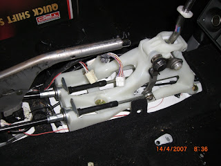
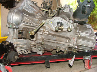 This is the transmission with the SMT hydraulics taken off... I've screwed the bolts back onto the tranny so I remembe where they go. The SMT shifter shaft is the shaft between the two top bolts... This is the thing that the shifter cables will ultimately connect onto and link the action between the manual shifter (inside the passenger cabin) and the position of the gears inside the transmission. The shifter shaft can be moved in the familiar H pattern of a manual car. This shaft will be replaced with a manual version.
The black rubbery looking thing to the left of the realy long bolt is the clutch actuator arm.. more pictures below to explain its operation.
 Clutch disengages (clutch pedal down)
 Clutch engages (clutch pedal up)
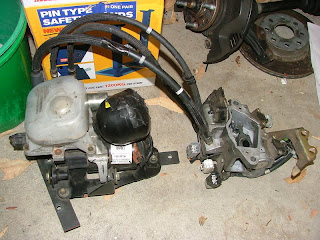 This is the SMT unit... the thing on the left of the picture is the HPU (the fluid tank I talked about is the thing with the white plastic cover on it. The cap is directly under the cover. The thing on the right is connected to the shifter shaft as well as the clutch actuator arm. The SMT ECU will control the mechanism on the right to coordinate the movement of the shifter shaft as well as the movement of the clutch actuator arm.
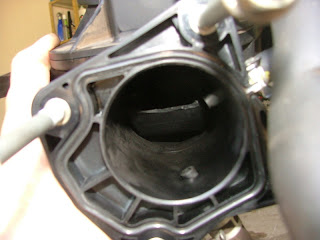 Now, this picture has nothing to do with the SMT, but you know that famous Turbo Intake Manifold EXPLOSION?? Well, it never blew a hole in my intake manifold, but it did break something inside the manifold!! Its a big piece too! Dremeled and cut at it for almost 3 hours to get it all out! Need to get this intake manifold pressure tested to ensure that it seals properly!
Ok, thats the latest... on the engine front, still waiting for speciality tools to arrive from the USA so I can get those head studs off!! Also need a special twist off socket for the one head stud which I rounded off when trying to undo with an Allen Key... moral of the story, dont use an Allen Key, use a proper 12 point (also know as double-hex, or triple-square), 10mm bit!!!
Anyway, onto the pics...
 This is the transmission with the SMT hydraulics taken off... I've screwed the bolts back onto the tranny so I remembe where they go. The SMT shifter shaft is the shaft between the two top bolts... This is the thing that the shifter cables will ultimately connect onto and link the action between the manual shifter (inside the passenger cabin) and the position of the gears inside the transmission. The shifter shaft can be moved in the familiar H pattern of a manual car. This shaft will be replaced with a manual version.
The black rubbery looking thing to the left of the realy long bolt is the clutch actuator arm.. more pictures below to explain its operation.
 Clutch disengages (clutch pedal down)
 Clutch engages (clutch pedal up)
 This is the SMT unit... the thing on the left of the picture is the HPU (the fluid tank I talked about is the thing with the white plastic cover on it. The cap is directly under the cover. The thing on the right is connected to the shifter shaft as well as the clutch actuator arm. The SMT ECU will control the mechanism on the right to coordinate the movement of the shifter shaft as well as the movement of the clutch actuator arm.
 Now, this picture has nothing to do with the SMT, but you know that famous Turbo Intake Manifold EXPLOSION?? Well, it never blew a hole in my intake manifold, but it did break something inside the manifold!! Its a big piece too! Dremeled and cut at it for almost 3 hours to get it all out! Need to get this intake manifold pressure tested to ensure that it seals properly!
Ok, thats the latest... on the engine front, still waiting for speciality tools to arrive from the USA so I can get those head studs off!! Also need a special twist off socket for the one head stud which I rounded off when trying to undo with an Allen Key... moral of the story, dont use an Allen Key, use a proper 12 point (also know as double-hex, or triple-square), 10mm bit!!!
Subscribe to:
Posts (Atom)